


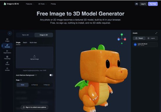
When independent hardware labs evaluate rapid additive manufacturing expenses, deploying a Free image to 3D workflow ensures immediate physical verification without incurring upfront computer-aided drafting retainers. By transforming planar industrial sketches or silhouette illustrations directly into manifold solid geometry, makers can test tactile prototypes on fused filament fabrication printers within hours of conceptual ideation. This operational speed eliminates traditional pre-manufacturing bottlenecks and allows workshops to iterate mechanical forms before committing tooling investments.
For small hardware startups, makerspaces, and digital fabricators, transforming a two-dimensional schematic into a physical object has historically represented a steep technical obstacle. Creating functional CAD geometry demands parametric modeling proficiency, precise dimensional constraints, and meticulous manual edge chamfering. When a workshop merely requires an early ergonomic grip check or an aesthetic housing prototype, dedicating twenty hours of professional CAD modeling is an expensive diversion of engineering bandwidth.
The Prototyping Bottleneck In Additive Fabrication Workflows
Physical manufacturing differs fundamentally from digital screen rendering because slicing engines evaluate volumetric mass rather than visual facades. Slicing software interprets surface meshes as rigid mathematical enclosures, calculating toolpaths for extrusion nozzles and ultraviolet exposure masks layer by layer. On stereolithography resin machines, even microscopic holes cause light bleed that cures unwanted resin islands inside the vat, ruining surface crispness. If an input file contains open boundaries, zero-thickness faces, or self-intersecting hulls, the slicer algorithm fails to compute perimeter infill, resulting in incomplete prints or printer head collisions.
Traditional photogrammetry attempts to solve this translation by requiring dozens of overlapping photographs taken under diffused lighting. Yet for initial concept drafts, physical prototypes do not yet exist to photograph. Algorithmic mesh generation bridges this limitation by hallucinating the complete spatial volume from a single high-clarity source illustration. In workshop bench tests, processing mechanical concepts through ImageTo3D AI generated closed polygon shells ready for slicer inspection in less than a minute, compressing early fabrication discovery cycles.
Algorithmic Depth Reconstruction From Planar Component Diagrams
The mathematical transition from pixel values to three-dimensional solids relies on signed distance field approximation and neural depth estimation. The generation engine analyzes stroke contrast, perspective clues, and perceived lighting angles across the graphic plane. From this optical data, it extrapolates rear and side contours to form an enclosed volumetric hull that mirrors the intended object silhouette.
Enforcing Watertight Manifold Boundaries For Slicer Stability
In 3D printing pipelines, the non-negotiable metric for geometry is manifold integrity, meaning every polygonal edge is shared by exactly two adjacent faces. When we compared the sliced gcode against the original sketch, neural mesh generation produced continuous outer shells that loaded cleanly into standard slicing software without triggering non-manifold geometry warnings. Slicers require watertight topology so the internal toolpath generator can differentiate solid plastic from hollow voids.
Generating assets via ImageTo3D AI at 1536 resolution produces dense surface facets that maintain smooth curvature along curved organic contours. Instead of generating hollow surface sheets that require extensive shell thickening in third-party sculpting suites, the platform yields solid geometry that can be exported directly as STL or converted to volumetric formats for additive manufacturing. This structural continuity ensures slicing engines calculate cohesive internal perimeters without generating erratic toolpaths.
Evaluating Shell Thickness And Structural Integrity During Slicing
A frequent failure mode in automated mesh generation occurs when thin peripheral details fall below the minimum feature threshold of standard extrusion nozzles. A 0.4mm nozzle printing at a 0.2mm layer height requires a minimum wall thickness of approximately 0.8mm to deposit two contiguous perimeter lines. When neural networks interpret fine graphic strokes, delicate ribbons can generate paper-thin geometry that snaps during post-print support removal.
Resolving Inverted Polygons And Surface Bubbling Prior To Printing
Wasted machine hours and burned filament frequently stem from invisible mesh defects such as inverted normal vectors. When normal vectors face inward, the slicer misinterprets exterior walls as internal voids, creating sporadic gaps along vertical perimeters. Inspecting the synthesized mesh under cross-sectional slicer previews reveals whether internal voids or surface bubbling exist inside the model hull.
Wasted an hour on non-manifold edge repairs during early testing taught our workshop team to inspect mesh boundaries before starting print jobs. If a generated component exhibits delicate overhangs that exceed forty-five degrees, makers can either reorient the part on the virtual build plate or configure dissolvable support interfaces. Catching that single discard during bed calibration prevents ruined print beds and saves costly engineering materials. Verifying support interface density in slicer simulation ensures delicate structural fins do not detach mid-print.
Step Sequence For Producing Print Ready STL Solids
To establish a reliable handoff between concept sketches and heated printer nozzles, digital fabricators should follow a disciplined preparation sequence:
- Prepare a high-contrast drawing showing the object in an isometric or straight orthographic angle against an isolated transparent or white background.
- Submit the concept image to ImageTo3D AI, selecting white mesh generation to focus strictly on physical volumetric mass rather than decorative surface coloration.
- Examine the generated 3D preview in the interactive viewport, rotating the geometry three hundred and sixty degrees to confirm rear contour coherence.
- Download the generated model as an STL file, then import it into your slicing application to inspect cross-sectional layer previews and wall perimeter counts.
- Configure internal gyroid infill patterns between fifteen and twenty-five percent to ensure isotropic structural strength across all print orientations.
- Apply minor scale adjustments to match desired physical dimensions, verify bed adhesion brim settings, and transmit the toolpath to the 3D printer.
Essential Guidelines For Preparing High Contrast Drawing Inputs
The geometric fidelity of an AI-synthesized model is bounded by the visual clarity of the input drawing. Illustrations characterized by noisy gradients, muddy shadows, or busy background clutter confuse depth inference models, causing surface artifacts and unwanted geometric ridges. For hardware components, line drawings featuring clean silhouette perimeters and consistent directional shading produce the cleanest volumetric enclosures.
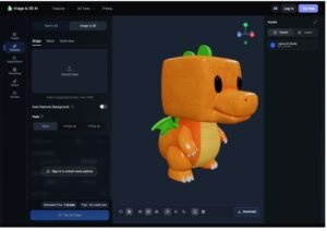
Where complex mechanical assemblies require multi-angle fidelity, combining orthogonal views delivers significantly superior spatial precision compared to single-angle guessing. Utilizing multi-view inputs—such as front, profile, and top perspective sketches—allows neural reconstruction engines to resolve hidden spatial dimensions with geometric authority, dramatically reducing the post-generation cleanup required in Blender or Meshmixer. This multi-angle alignment provides slicers with dependable geometric proportions that mirror physical design intent.
Real World Boundaries In AI Driven Additive Manufacturing
While algorithmic 3D reconstruction provides unprecedented prototyping velocity, makers must acknowledge the operational boundaries of neural geometry. AI generation is fundamentally probabilistic; it does not comprehend mechanical tolerances, threaded screw pitches, or sliding press-fit clearances. Attempting to generate interlocking gear trains or load-bearing snap-fit joints directly from a single 2D sketch will inevitably yield inaccurate mating surfaces that fail under mechanical stress.
The genuine value of rapid 3D generation lies in the rapid tactile verification of form, ergonomics, and aesthetic scale. Relying on a Free & No sign up image to 3D workflow allows a product designer to hold three physical iterations of an ergonomic enclosure within an afternoon, validating hand-feel before committing to precision engineering in SolidWorks or Fusion 360. By automating early tactile maquettes, digital fabrication studios minimize upfront risk and accelerate development from initial doodle to finished hardware.

